Features
All Creo solid models are made up of features. This section describes how to program on the feature level using Creo Object TOOLKIT C++.
The actual type of pfcSolid objects is wfcWSolid and pfcFeature object is wfcWFeature. Therefore, the methods from wfcWFeature and wfcWSolid become available to these objects only after applying wfcWFeature::cast or wfcWSolid::cast. You must check that this cast does not return a null pointer.
Access to Features
Methods Introduced:
The methods pfcFeature::ListChildren and pfcFeature::ListParents return a sequence of features that contain all the children or parents of the specified feature.
To get the first feature in the specified group access the method pfcFeatureGroup::GetGroupLeader.
The methods pfcFeaturePattern::GetPatternLeader and the method pfcFeaturePattern::ListMembers return features that make up the specified feature pattern. See the section Feature Groups and Patterns for more information on feature patterns.
The method pfcSolid::ListFailedFeatures returns a sequence that contains all the features that failed regeneration.
The method wfcWSolid::ListChildOfExternalFailedFeatures returns a list of elements, where each element is a child of an external failed feature.
The method wfcWSolid:: ListChildOfFailedFeatures returns a list of elements, where each element is a child of a failed feature.
The method pfcSolid::ListFeaturesByType returns a sequence of features contained in the model. You can specify which type of feature to collect by passing in one of the pfcFeatureType enumeration objects, or you can collect all features by passing void null as the type. If you list all features, the resulting sequence will include invisible features that Creo creates internally. Use the method’s VisibleOnly argument to exclude them.
The method pfcSolid::GetFeatureById returns the feature object with the corresponding integer identifier.
A feature can be edited with the Edit Definition command in Creo Parametric. The method pfcBaseSession::QueryFeatureEdit returns a list of all the features that are currently being edited by the Edit Definition command.
Feature Information
Methods Introduced:
The enumeration classes pfcFeatureType and pfcFeatureStatus provide information for a specified feature. The following methods specify this information:
•  pfcFeature::GetFeatType—Returns the type of a feature.
•  pfcFeature::GetStatus—Returns whether the feature is suppressed, active, or failed regeneration.
The other methods that gather feature information include the following:
•  pfcFeature::GetIsVisible—Identifies whether the specified feature will be visible on the screen. The method distinguishes visible features from internal features. Internal features are invisible features used for construction purposes.
•  pfcFeature::GetIsReadonly—Identifies whether the specified feature can be modified.
•  pfcFeature::GetIsEmbedded—Specifies whether the specified feature is an embedded datum.
•  pfcFeature::GetNumber—Returns the feature regeneration number. This method returns void null if the feature is suppressed.
The method pfcFeature::GetFeatTypeName returns a string representation of the feature type.
The method pfcFeature::GetFeatSubType returns a string representation of the feature subtype, for example, "Extrude" for a protrusion feature.
The method pfcRoundFeat::GetIsAutoRoundMember determines whether the specified round feature is a member of an Auto Round feature.
The method wfcWFeature::IsElementVisible determines whether the specified element is visible.
The method wfcWFeature::IsElementIncomplete determines whether the specified element is incomplete. If a feature is incomplete, you can use this method to find out which element in the tree is incomplete.
The method wfcWFeature::IsElementVisible retrieves the bit status flag object of the feature.
The method wfcWFeature::GetStatusFlag retrieves the bit status flag object of the feature.
The method wfcWSolid::CreateZoneSectionFeature creates a zone feature. The input arguments are:
•  RefData—The references to create the zone feature.
•  ZoneName—The name of the zone feature.
The method wfcZoneFeatureReference::Create creates an object of type wfcZoneFeatureReference that contains information about the zone references for the specified feature.
Use the method wfcZoneFeatureReference::GetPlaneId to retrieve the geometric ID of the reference zone plane. The method wfcZoneFeatureReference::SetPlaneId sets the geometric ID for the reference zone plane.
The method wfcZoneFeatureReference::GetOperation gets the value of the operation, where 0 specifies intersection of half spaces that is, the AND operator and 1 specifies union of half spaces that is, the OR operator. Use the method wfcZoneFeatureReference::SetOperation to set the value of the operation.
The method wfcZoneFeatureReference::GetMemberIdTable returns a sequence of component identifiers that form the path to the part to which the reference plane belongs.
Use the method wfcZoneFeatureReference::SetMemberIdTable to set the path to the part for the reference plane.
Note
When the feature is owned by a part, pass the value NULL.
The methods wfcZoneFeatureReference::GetFlip and wfcZoneFeatureReference::SetFlip retrieve and set the side of the plane where the model is kept. True indicates positive normal of the plane and false indicates the opposite side.
The method wfcWFeature::GetZoneFeatureReferences returns the references used to create the zone feature.
The method wfcWFeature::GetZoneFeaturePlaneData returns the planes used to create the zone feature.
Use the method wfcWFeature::GetZoneXSectionGeometry to retrieve the array of cross sections in the specified zone feature.
The method wfcWFeature::IsInFooter checks if the specified feature is currently located in the model tree footer. The footer is a section of the model tree that lists certain types of features such as, component interfaces, annotation features, zones, reference features, publish geometry, and analysis feature. The features in the footer are always regenerated at the end of the feature list. You can move features, such as, reference features, annotation features, and so on, to the footer. Some features, such as, component interfaces, zones, and so on, are automatically placed in the footer. Refer to the Creo Parametric online Help for more information on footer. Refer to the Creo Parametric online Help for more information on footer.
Use the method wfcWFeature::MoveToFooter to move the specified feature into the model tree footer.
Use the method wfcWFeature::MoveFromFooter to move the specified feature out of the model tree footer.
Feature Inquiry
Methods Introduced:
The method wfcFeatureStatusFlag::GetFeatureId retrieves the feature id of the feature in a part or an assembly.
The method wfcFeatureStatusFlag::GetIsActive returns true if the feature is active in a part or an assembly.
The method wfcFeatureStatusFlag::GetIsInactive returns true if the feature is inactive in a part or an assembly. If it returns false, it is an active feature.
The method wfcFeatureStatusFlag::GetIsChildOfExternalFailed returns true if the feature is a child of an external failed feature in a part or an assembly.
The method wfcFeatureStatusFlag::GetIsChildOfFailed returns true if the feature is a child of a failed feature in a part or an assembly.
The method wfcFeatureStatusFlag::GetIsFailed returns true if the feature failed regeneration in a part or an assembly.
The method wfcFeatureStatusFlag::GetIsFamtabSuppressed returns true if the feature is suppressed due to the family table settings.
The method wfcFeatureStatusFlag::GetIsInvalid returns true if the feature status could not be retrieved.
The method wfcFeatureStatusFlag::GetIsProgramSuppressed returns true if the feature is suppressed due to a Pro/PROGRAM functionality.
The method wfcFeatureStatusFlag::GetIsSimprepSuppressed returns true if the feature is suppressed due to a simplified representation.
The method wfcFeatureStatusFlag::GetIsSuppressed returns true if the feature is suppressed.
The method wfcFeatureStatusFlag::GetIsUnregenerated returns true if the feature is active and which has not yet been regenerated. This is due to a regeneration failure or if the status is obtained during the regeneration process.
Feature Operations
Methods Introduced:
The method pfcSolid::ExecuteFeatureOps causes a sequence of feature operations to run in order. Feature operations include suppressing, resuming, reordering, and deleting features. The optional pfcRegenInstructions argument specifies whether the user will be allowed to fix the model if a regeneration failure occurs.
Note
The method pfcSolid::ExecuteFeatureOps is not supported in the No-Resolve mode. It throws an exception pfcXToolkitBadContext. To switch back to the Pro/ENGINEER Wildfire 4.0 behavior in the Resolve mode, set the configuration option regen_failure_handling to resolve_mode in the Creo Parametric session. Refer to the Solid Operations section in the Solid section for more information on the No-Resolve mode.
You can create an operation that will delete, suppress, reorder, or resume certain features using the methods in the interface pfcFeature. Each created operation must be passed as a member of the pfcFeatureOperations object to the method pfcSolid::ExecuteFeatureOps. You can create a sequence of the pfcFeatureOperations object using the method pfcFeatureOperations::create.
Some of the operations have specific options that you can modify to control the behavior of the operation:
•  Clip—Specifies whether to delete or suppress all features after the selected feature. By default, this option is false.
Use the methods pfcDeleteOperation::SetClip and pfcSuppressOperation::SetClip to modify this option.
•  AllowGroupMembers—If this option is set to true and if the feature to be deleted or suppressed is a member of a group, then the feature will be deleted or suppressed out of the group. If this option is set to false, then the entire group containing the feature is deleted or suppressed. By default, this option is false. It can be set to true only if the option Clip is set to true.
Use the methods pfcSuppressOperation::SetAllowGroupMembers and pfcDeleteOperation::SetAllowGroupMembers to modify this option.
•  AllowChildGroupMembers—If this option is set to true and if the children of the feature to be deleted or suppressed are members of a group, then the children of the feature will be individually deleted or suppressed out of the group. If this option is set to false, then the entire group containing the feature and its children is deleted or suppressed. By default, this option is false. It can be set to true only if the options Clip and AllowGroupMembers are set to true.
Use the methods pfcSuppressOperation::SetAllowChildGroupMembers and pfcDeleteOperation::SetAllowChildGroupMembers to modify this option.
•  KeepEmbeddedDatums—Specifies whether to retain the embedded datums stored in a feature while deleting the feature. By default, this option is false.
Use the method pfcDeleteOperation::SetKeepEmbeddedDatums to modify this option.
•  WithParents—Specifies whether to resume the parents of the selected feature.
Use the method pfcResumeOperation::SetWithParents to modify this option.
•  BeforeFeat—Specifies the feature before which you want to reorder the features.
Use the method pfcReorderBeforeOperation::SetBeforeFeat to modify this option.
•  AfterFeat—Specifies the feature after which you want to reorder the features.
Use the method pfcReorderAfterOperation::SetAfterFeat to modify this option.
Use the methods wfcWSolid::DeleteFeatures, wfcWSolid::SuppressFeatures, wfcWSolid::ResumeFeatures and wfcWSolid::ReorderFeatures to delete, suppress, resume and reorder a list of features. The input parameters for all the methods are:
•  FeatIDs—The list of IDs for the features to be deleted, suppressed, reordered or resumed.
•  Options—The list of options to be used. This input argument is not applicable to the method wfcWSolid::ReorderFeatures.
•  Instrs—Regeneration instructions to be used.
The reorder method takes its second input parameter as:
•  NewFeatNum—The intended location of the first feature in the specified list.
Feature Groups and Patterns
Patterns are treated as features in Creo applications. A feature type, pfcFEATTYPE_PATTERN_HEAD, is used for the pattern header feature.
Note
The pattern header feature is not treated as a leader or a member of the pattern by the methods described in the following section.
Methods Introduced:
The method pfcFeature::GetGroup returns a handle to the local group that contains the specified feature.
To get the first feature in the specified group call the method pfcFeatureGroup::GetGroupLeader.
The methods pfcFeaturePattern::GetPatternLeader and pfcFeaturePattern::ListMembers return features that make up the specified feature pattern.
A pattern is composed of a pattern header feature and a number of member features. You can pattern only a single feature. To pattern several features, create a local group and pattern this group.
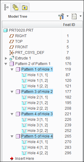
You can also create a pattern of pattern. This creates a multiple level pattern. From Creo Parametric 2.0 M170 onward, for a pattern of pattern, the method pfcFeaturePattern::ListMembers returns all the pattern header features created at the first level.
For example, consider a model where a pattern of pattern has been created. The model tree is as shown below:
Image
The method pfcFeaturePattern::ListMembers returns the pattern header features with following IDs for a pattern of pattern:
•  119
•  177
•  221
•  265
The methods pfcFeature::GetPattern and pfcFeatureGroup::GetPattern return the pfcFeaturePattern object that contains the corresponding pfcFeature or pfcFeatureGroup. Use the method pfcSolid::CreateLocalGroup to take a sequence of features and create a local group with the specified name. To delete a pfcFeaturePattern object, call the method pfcFeaturePattern::Delete.
User Defined Features
Groups in Creo represent sets of contiguous features that act as a single feature for specific operations. Individual features are affected by most operations while some operations apply to an entire group:
•  Suppress
•  Delete
•  Layers
•  Patterning
User defined Features (UDFs) are groups of features that are stored in a file. When a UDF is placed in a new model the created features are automatically assigned to a group. A local group is a set of features that have been specifically assigned to a group to make modifications and patterning easier.
Note
All methods in this section can be used for UDFs and local groups.
Read Access to Groups and User Defined Features
Methods Introduced:
User defined features (UDF’s) are groups of features that can be stored in a file and added to a new model. A local group is similar to a UDF except it is available only in the model in which is was created.
The method pfcFeatureGroup::GetUDFName provides the name of the group for the specified group instance. A particular group definition can be used more than once in a particular model.
If the group is a family table instance, the method pfcFeatureGroup::GetUDFInstanceName supplies the instance name.
The method pfcFeatureGroup::ListUDFDimensions traverses the dimensions that belong to the UDF. These dimensions correspond to the dimensions specified as variables when the UDF was created. Dimensions of the original features that were not variables in the UDF are not included unless the UDF was placed using the Independent option.
The method pfcUDFDimension::GetUDFDimensionName provides access to the dimension name specified when the UDF was created, and not the name of the dimension in the current model. This name is required to place the UDF programmatically using the method pfcSolid::CreateUDFGroup.
Creating Features from UDFs
Method Introduced:
The method pfcSolid::CreateUDFGroup is used to create new features by retrieving and applying the contents of an existing UDF file. It is equivalent to the Creo command Feature, Create, User Defined.
To understand the following explanation of this method, you must have a good knowledge and understanding of the use of UDF’s in Creo applications. PTC recommends that you read about UDF’s in theCreo online help, and practice defining and using UDF’s in Creo application before you attempt to use this method.
When you create a UDF interactively, Creo application prompts you for the information it needs to fix the properties of the resulting features. When you create a UDF from Creo Object TOOLKIT C++, you can provide some or all of this information programmatically by filling several compact data classes that are inputs to the method pfcSolid::CreateUDFGroup.
During the call to pfcSolid::CreateUDFGroup, Creo application prompts you for the following:
•  Information required by the UDF that was not provided in the input data structures
•  Correct information to replace erroneous information
Such prompts are a useful way of diagnosing errors when you develop your application. This also means that, in addition to creating UDF’s programmatically to provide automatic synthesis of model geometry, you can also use pfcSolid::CreateUDFGroup to create UDF’s semi-interactively. This can simplify the interactions needed to place a complex UDF making it easier for the user and less prone to error.
Creating UDFs
Creating a UDF requires the following information:
•  Name—The name of the UDF you are creating and the instance name if applicable.
•  Dependency—Specify if the UDF is independent of the UDF definition or is modified by the changers made to it.
•  Scale—How to scale the UDF relative to the placement model.
•  Variable Dimension—The new values of the variables dimensions and pattern parameters, those whose values can be modified each time the UDF is created.
•  Dimension Display—Whether to show or blank non-variable dimensions created within the UDF group.
•  References—The geometrical elements that the UDF needs in order to relate the features it contains to the existing models features. The elements correspond to the picks that Creo application prompts you for when you create a UDF interactively using the prompts defined when the UDF was created. You cannot select an embedded datum as the UDF reference.
•  Parts Intersection—When a UDF that is being created in an assembly contains features that modify the existing geometry you must define which parts are affected or intersected. You also need to know at what level in an assembly each intersection is going to be visible.
•  Orientations—When a UDF contains a feature with a direction that is defined with respect to a datum plane Creo must know what direction the new feature will point to. When you create such a UDF interactively, Creo application prompts you for this information with a flip arrow.
•  Quadrants—When a UDF contains a linearly placed feature that references two datum planes to define it’s location in the new model Creo application prompts you to pick the location of the new feature. This is determined by which side of each datum plane the feature must lie. This selection is referred to as the quadrant because the are four possible combinations for each linearly place feature.
Creo Object TOOLKIT C++ uses a special class that prepares and sets all the options and passes them to Creo application.
Creating Interactively Defined UDFs
Method Introduced:
This static method is used to create an instructions object that can be used to prompt a user for the required values that will create a UDF interactively.
Creating a Custom UDF
Method Introduced:
The method pfcUDFCustomCreateInstructions::Create creates a UDFCustomCreateInstructions object with a specified name. To set the UDF creation parameters programmatically you must modify this object as described below. The members of this class relate closely to the prompts Creo gives you when you create a UDF interactively. PTC recommends that you experiment with creating the UDF interactively using Creo application before you write the Creo Object TOOLKIT C++ code to fill the structure.
The method wfcWUDFCustomCreateInstructions::Create creates a WUDFCustomCreateInstructions object with a specified name.
Setting the Family Table Instance Name
Methods Introduced:
If the UDF contains a family table, this field can be used to select the instance in the table. If the UDF does not contain a family table, or if the generic instance is to be selected, the do not set the string.
Setting Dependency Type
Methods Introduced:
The pfcUDFDependencyType object represents the dependency type of the UDF. The choices correspond to the choices available when you create a UDF interactively. This enumerated type takes the following values:
•  pfcUDFDEP_INDEPENDENT
•  pfcUDFDEP_DRIVEN
Note
pfcUDFDEP_INDEPENDENT is the default value, if this option is not set.
Setting Scale and Scale Type
Methods Introduced:
ScaleType specifies the length units of the UDF in the form of the pfcUDFScaleType object. This enumerated type takes the following values:
•  pfcUDFSCALE_SAME_SIZE
•  pfcUDFSCALE_SAME_DIMS
•  pfcUDFSCALE_CUSTOM
•  pfcUDFSCALE_nil
Note
The default value is pfcUDFSCALE_SAME_SIZE if this option is not set.
Scale specifies the scale factor. If the ScaleType is set to UDFSCALE_CUSTOM, pfcSetScale assigns the user defined scale factor. Otherwise, this attribute is ignored.
Setting the Appearance of the Non UDF Dimensions
Methods Introduced:
The pfcUDFDimensionDisplayType object sets the options in Creo for determining the appearance in the model of UDF dimensions and pattern parameters that were not variable in the UDF, and therefore cannot be modified in the model. This enumerated type takes the following values:
•  pfcUDFDISPLAY_NORMAL
•  pfcUDFDISPLAY_READ_ONLY
•  pfcUDFDISPLAY_BLANK
Note
The default value is pfcUDFDISPLAY_NORMAL if this option is not set.
Setting the Variable Dimensions and Parameters
Methods Introduced:
pfcUDFVariantValues class represents an array of variable dimensions and pattern parameters.
Use pfcUDFVariantValues::create to create an empty object and then use pfcUDFVariantValues::insert to add pfcUDFVariantPatternParam or pfcUDFVariantDimension objects one by one.
pfcUDFVariantDimension::Create is a static method creating a pfcUDFVariantDimension. It accepts the following parameters:
•  Name—The symbol that the dimension had when the UDF was originally defined not the prompt that the UDF uses when it is created interactively. To make this name easy to remember, before you define the UDF that you plan to create with the Creo Object TOOLKIT C++, you should modify the symbols of all the dimensions that you want to select to be variable. If you get the name wrong, pfcCreateUDFGroup will not recognize the dimension and prompts the user for the value in the usual way does not modify the value.
•  DimensionValue—The new value.
If you do not remember the name, you can find it by creating the UDF interactively in a test model, then using the pfcFeatureGroup::ListUDFDimensions and pfcUDFDimension::GetUDFDimensionName to find out the name.
pfcUDFVariantPatternParam::Create is a static method which creates a pfcUDFVariantPatternParam. It accepts the following parameters:
•  name—The string name that the pattern parameter had when the UDF was originally defined
•  patternparam—The new value.
After the pfcUDFVariantValues object has been compiled, use pfcUDFCustomCreateInstructions::SetVariantValues to add the variable dimensions and parameters to the instructions.
Use the method wfcWSession::GetUDFDataDefaultVariableParameters to obtain an array of available variant parameters and/or annotation values that can optionally be set when placing this UDF. The input arguments to this method are:
•  name
•  instance
The method wfcUDFVariableParameter::Create enables you to create a variable parameter object using the UDF data. The input arguments are:
•  Name—Specify the name of the variable parameter.
•  ItemType—Specify the item type of the parameter using the enumerated type pfcModelItemType.
•  ItemId—Specify the item ID of the variable parameter.
The methods wfcUDFVariableParameter::GetName and wfcUDFVariableParameter::SetName—get and set the name or the symbol of the variant parameter or annotation value.
The methods wfcUDFVariableParameter::GetItemType and wfcUDFVariableParameter::SetItemType—get and set the item type of the variant parameter or annotation value.
The methods wfcUDFVariableParameter::GetItemId and wfcUDFVariableParameter::SetItemId—get and set the item id of the variant parameter or annotation value.
The methods wfcUDFVariableParameter::GetValue and wfcUDFVariableParameter::SetValue—get and set the default value for the variant parameter or annotation value.
Use the method wfcWUDFCustomCreateInstructions::SetVariableParameters to set the variable parameter sequence for a UDF feature.
Use the method wfcWUDFCustomCreateInstructions::GetVariableParameters to retrieve the variable parameter sequence.
Setting the User Defined References
Methods Introduced:
UDFReferences class represents an array of element references. Use pfcUDFReferences::create to create an empty object and then use pfcUDFReferences::insert to add pfcUDFReference objects one by one.
The method pfcUDFReference::Create is a static method creating a UDFReference object. It accepts the following parameters:
•  PromptForReference—The prompt defined for this reference when the UDF was originally set up. It indicates which reference this structure is providing. If you get the prompt wrong, pfcSolid::CreateUDFGroup will not recognize it and prompts the user for the reference in the usual way.
•  ReferenceItem—Specifies the pfcSelection object representing the referenced element. You can set pfcSelection programmatically or prompt the user for a selection separately. You cannot set an embedded datum as the UDF reference.
There are two types of references:
  Internal—The referenced element belongs directly to the model that will contain the UDF. For an assembly, this means that the element belongs to the top level.
  External—The referenced element belongs to an assembly member other than the placement member.
To set the reference type, use the method pfcUDFReference::SetIsExternal.
To set the item to be used for reference, use the method pfcUDFReference::SetReferenceItem.
After the UDFReferences object has been set, use pfcUDFCustomCreateInstructions::SetReferences to add the program-defined references.
Setting the Assembly Intersections
Methods Introduced:
The pfcUDFAssemblyIntersections class represents an array of element references.
Use pfcUDFAssemblyIntersections::create to create an empty object and then use pfcUDFAssemblyIntersections::insert to add pfcUDFAssemblyIntersection objects one by one.
pfcUDFAssemblyIntersection::Create is a static method creating a pfcUDFReference object. It accepts the following parameters:
•  ComponentPath—Is an xintsequence_ptr type object representing the component path of the part to be intersected.
•  Visibility level—The number that corresponds to the visibility level of the intersected part in the assembly. If the number is equal to the length of the component path the feature is visible in the part that it intersects. If Visibility level is 0, the feature is visible at the level of the assembly containing the UDF.
pfcUDFAssemblyIntersection::SetInstanceNames sets an array of names for the new instances of parts created to represent the intersection geometry. This method accepts the following parameters:
•  instance names—is a xstringsequence_ptr type object representing the array of new instance names.
After the pfcUDFAssemblyIntersections object has been set, use pfcUDFCustomCreateInstructions::SetIntersections to add the assembly intersections.
External Symbol: Parameters
The data object for external symbol parameters is wfcUDFExternalParameter.
Methods Introduced:
The method wfcUDFExternalParameter::Create enables you to create an external parameter symbol object required by a UDF. The input arguments are:
•  name—Specify the name of the external parameter symbol.
•  parameter—Specify the parameter that is used to resolve this external symbol in the placement model.
The methods wfcUDFExternalParameter::GetParameter and wfcUDFExternalParameter::SetParameter retrieve and set the parameter used to resolve the external symbol.
The methods wfcUDFExternalParameter::GetPrompt and wfcUDFExternalParameter::SetPrompt retrieve and set the prompt for the external parameter symbol.
Use the method wfcWUDFCustomCreateInstructions::SetExternalParameters to the set the external parameters for a UDF feature.
Use the method wfcWUDFCustomCreateInstructions::GetExternalParameters to retrieve the external parameters.
External Symbol: Dimensions
The data object for external symbol parameters is wfcUDFExternalDimension.
Methods Introduced:
The method wfcUDFExternalDimension::Create enables you to create an external dimension symbol object required by a UDF. The input arguments are:
•  name—Specify the name of the external dimension symbol.
•  dimension—Specify the dimension that is used to resolve this external symbol in the placement model.
The methods wfcUDFExternalDimension::GetDimension and wfcUDFExternalDimension::SetDimension retrieve and set the dimension used to resolve the external symbol.
The methods wfcUDFExternalDimension::GetPrompt and wfcUDFExternalDimension::SetPrompt retrieve and set the prompt used for the external dimension symbol.
Use the method wfcWUDFCustomCreateInstructions::SetExternalDimensions to the set the external dimensions for a UDF feature.
Use the method wfcWUDFCustomCreateInstructions::GetExternalDimensions to retrieve the external dimensions.
Setting Orientations
Methods Introduced:
pfcUDFOrientations class represents an array of orientations that provide the answers to Creo applications prompts that use a flip arrow. Each term is a pfcUDFOrientation object that takes the following values:
•  pfcUDFORIENT_INTERACTIVE—Prompt for the orientation using a flip arrow.
•  pfcUDFORIENT_NO_FLIP—Accept the default flip orientation.
•  pfcUDFORIENT_FLIP—Invert the orientation from the default orientation.
Use pfcUDFOrientations::create to create an empty object and then use pfcUDFOrientations::insert to add pfcUDFOrientation objects one by one.
The order of orientations should correspond to the order in which Creo prompts for them when the UDF is created interactively. If you do not provide an orientation the default value NO_FLIP is used.
After the pfcUDFOrientations object has been set use pfcUDFCustomCreateInstructions::SetOrientations to add the orientations.
Setting Quadrants
Methods Introduced:
The method pfcUDFCustomCreateInstructions::SetQuadrants sets an array of points, which provide the X, Y, and Z coordinates that correspond to the picks answering the Creo prompts for the feature positions. The order of quadrants should correspond to the order in which Creo prompts for them when the UDF is created interactively.
Setting the External References
Methods Introduced:
The method pfcUDFCustomCreateInstructions::SetExtReferences sets an external reference assembly to be used when placing the UDF. This will be required when placing the UDF in the component using references outside of that component. References could be to the top level assembly of another component.